Service explanation for JA-68 1 The JA-68 universal output module The JA-68 is a universal output module designed for the Jablotron systems of the JA-80 OASiS, JA-63 Profi and JA-65 Maestro series. The module provides eight factory pre-programmed semi-conductor outputs and a switch-over relay output. The relay can be configured...
JA-68
There are no products in these categories. Shop on.
Service explanation for JA-68
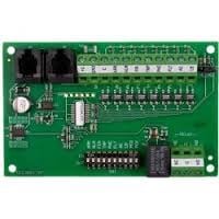
1 The JA-68 universal output module
The JA-68 is a universal output module designed for the Jablotron systems of the JA-80 OASiS, JA-63 Profi and JA-65 Maestro series. The module provides eight factory pre-programmed semi-conductor outputs and a switch-over relay output. The relay can be configured using 10 DIP switches that allow you to command for multiple functions. There is no limit to the number of the JA-68 modules used in the system. The JA-68 can be combined with GSM, LAN or PSTN (landline) dialers.
The module is designed to be placed in the housing of the PBX.
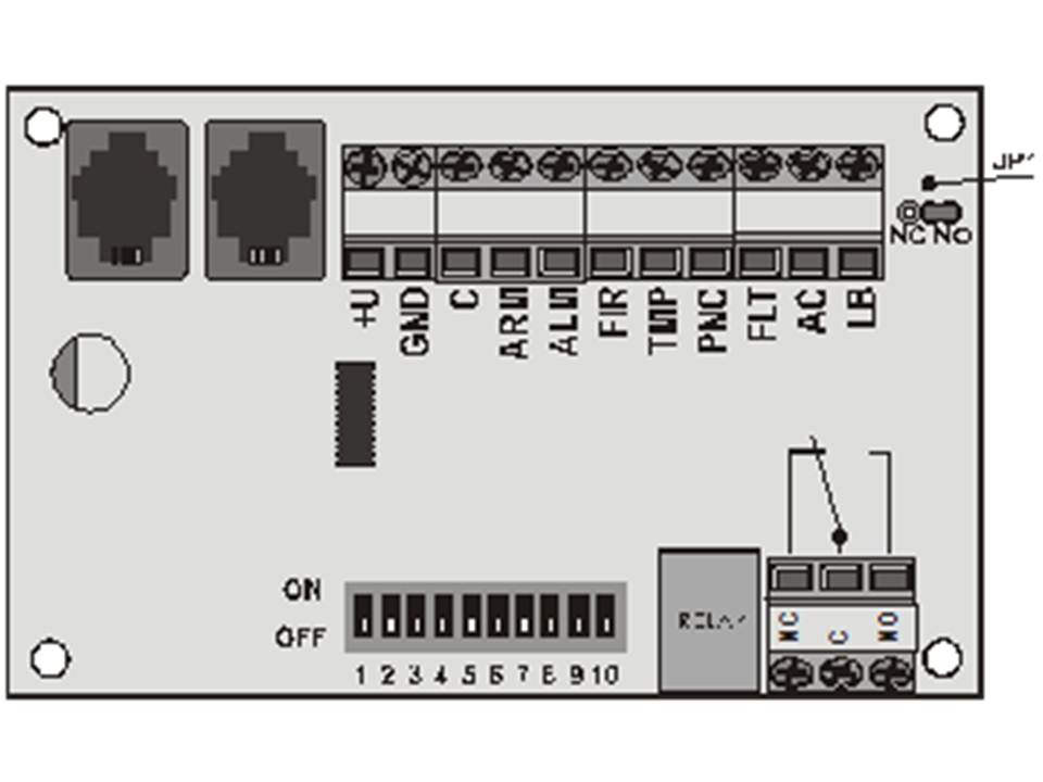
2 Semi-conductor outputs
All semi-conductor outputs are switchable to a common terminal marked "C". The switch ON/OFF logic can be reversed by setting a jumper JP1 to the NC position (the default is NO).
Description of the codes:
| Code | Functie |
| +U | Positive power supply of the digital bus (limited to 200 mA) |
| GND | Negative pole of the power supply |
| C | Common code (for all semi-conductor outputs) |
| ARM | All-set status (A or AB or ABC) |
| ALM | Burglar alarm |
| FIR | Fire alarm |
| TMP | Sabotage alarm |
| PNC | Panic alarm |
| FLT | Fault message (general faults, radio communication faults, backup battery faults |
| AC | Socket (230V) power supply error |
| LB | Low battery indication (applies to wireless devices, such as detectors, control panels, sirens or thermostats) |
Tabel 1
3 Relay configuration
The relay is configurable via a set of 10 DIP switches (see Table 2). The relay works with OR logic: It switches on if there is at least one activated preset function on it.
Example: Setting switches 2,3,4 and 5 to ON causes the relay to indicate: burglary, fire, tamper or panic alarms. The relay switches ON when any of the four mentioned states of alarm are triggered.
DIP switches commands:
| Nummer | Label | Functie |
| 1 | ARM | All set |
| 2 | ALM | Burglar alarm |
| 3 | FIR | Fire alarm |
| 4 | TMP | Sabotage alarm |
| 5 | PNC | Panic alarm |
| 6 | FLT | System disruption |
| 7 | AC | Power supply error |
| 8 | LB | Low battery |
| 9 | PGX | Central PGX output |
| 10 | PGY | Central PGY output |
Tabel 2
Description of relay codes:
| Label | Beschrijving |
| NC | Normally closed relay |
| C | Common relay contact |
| NO | Normal open relay contact |
Note: There is a minimum output activation time of 10 seconds for each of the 8 + 1 outputs